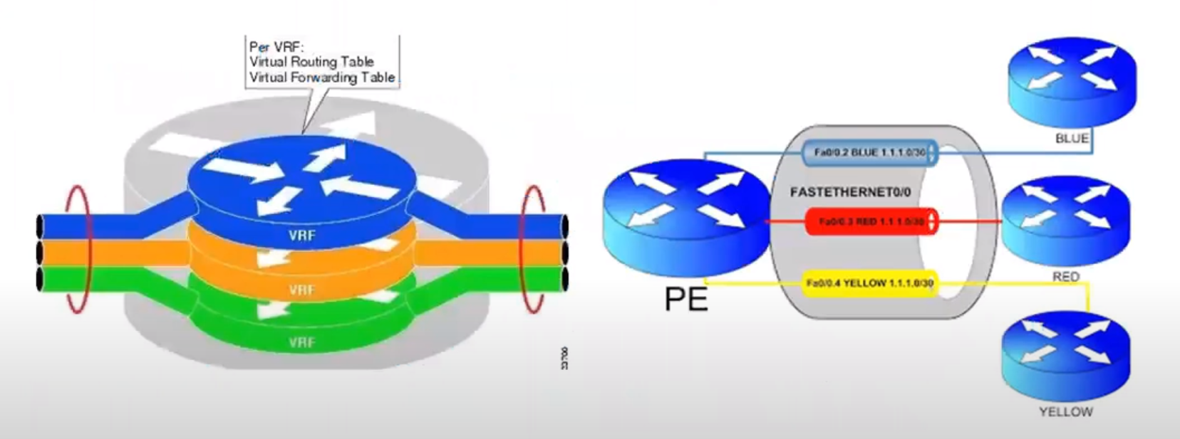
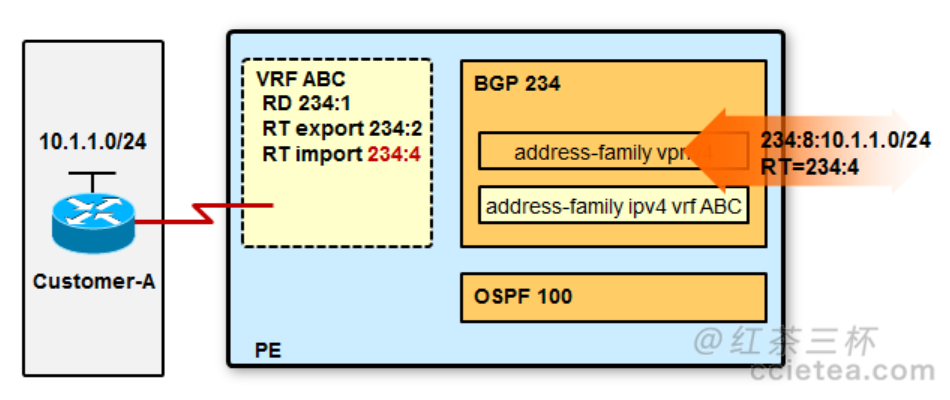
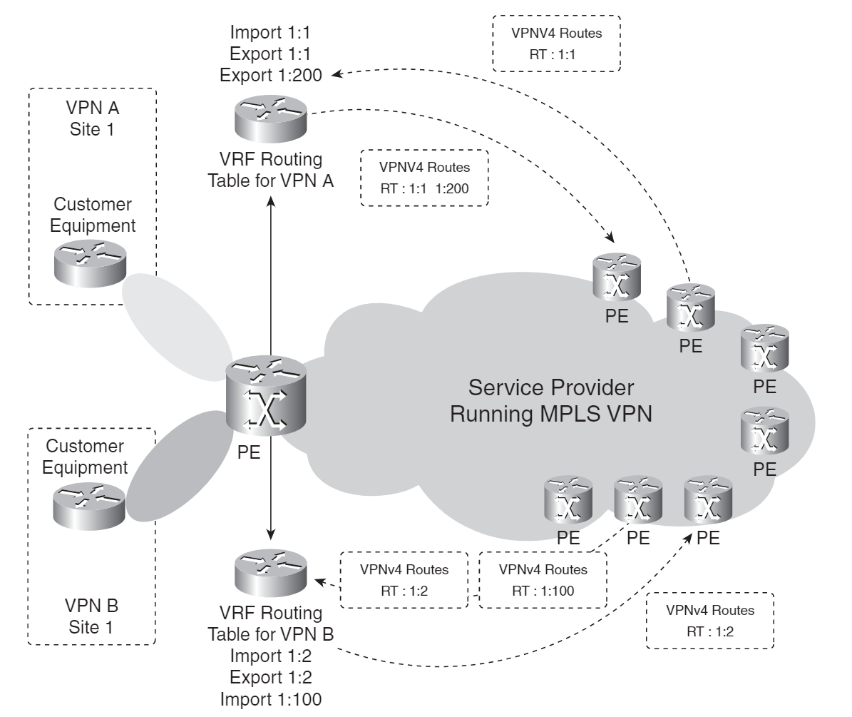
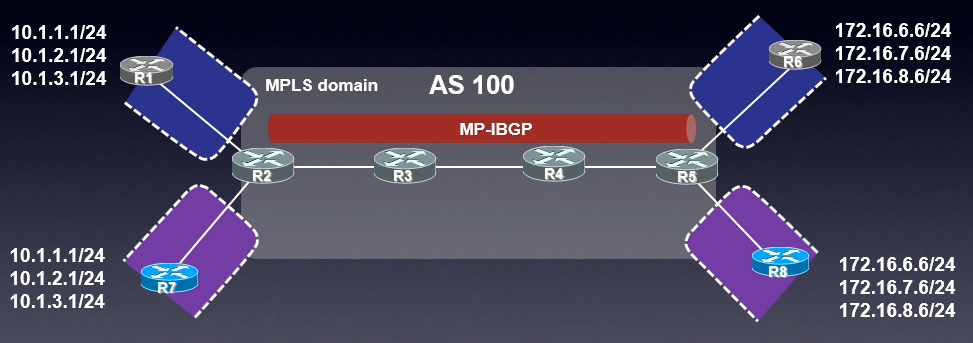
VRF全称为Virtual Routing and Forwarding,翻译成虚拟路由及转发,它是一种VPN路由和转发实例。一台PE路由器,可能同时连接了多个VPN用户,这些用户(的路由)彼此之间需要相互隔离,那么这时候就用到了VRF。PE路由器上每一个VPN都有一个VRF。PE路由器除了维护全局IP路由表以外,还为每个VRF维护一张独立的IP路由表,这张路由表称为VRF路由表。必须注意,前面说到的全局IP路由表和每个VRF的路由表都是相互独立或相互隔离的。
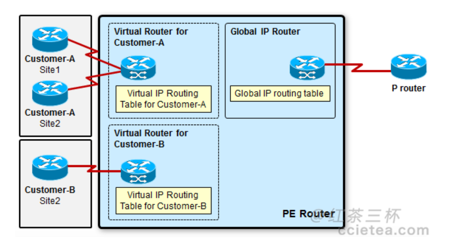
一个PE路由器可以连接不同的VPN客户,使用类似于虚拟路由器(VRF实例)的概念,来进行逻辑上的区分,比如上图中的Virtual route for A和Virtual route for B。这些客户甚至可能使用相同的地址空间,比如客户A和B都是用192.168.0.0作为内网的IP地址,在一台PE上使用VRF路由表,将不同客户的路由进行逻辑上的隔离。这里Virtual路由表是相对我们全局IP路由的概念,从Global接口上学习到的路由,放入全局路由表,从VRF接口上学习到的路由,放入相对应的VRF路由表。不同的Virtual路由表完全隔离。
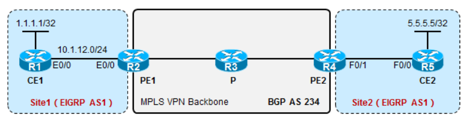
R5: router ospf 1 router-id 5.5.5.5 network 5.5.5.5 0.0.0.0 area 0 network 10.1.45.5 0.0.0.0 area 0 PE-CE之间的邻居和路由结果如下: R2#show ip eigrp vrf CISCO neighbors EIGRP-IPv4 Neighbors for AS(1) VRF(CISCO) H Address Interface Hold Uptime SRTT RTO Q Seq (sec) (ms) Cnt Num 0 10.1.12.1 Et0/0 11 04:04:47 9 100 0 3
R2#show ip route vrf CISCO Routing Table: CISCO Codes: L - local, C - connected, S - static, R - RIP, M - mobile, B - BGP D - EIGRP, EX - EIGRP external, O - OSPF, IA - OSPF inter area N1 - OSPF NSSA external type 1, N2 - OSPF NSSA external type 2 E1 - OSPF external type 1, E2 - OSPF external type 2 i - IS-IS, su - IS-IS summary, L1 - IS-IS level-1, L2 - IS-IS level-2 ia - IS-IS inter area, * - candidate default, U - per-user static route o - ODR, P - periodic downloaded static route, H - NHRP, l - LISP a - application route + - replicated route, % - next hop override, p - overrides from PfR
Gateway of last resort is not set
1.0.0.0/24 is subnetted, 1 subnets D 1.1.1.0 [90/409600] via 10.1.12.1, 03:30:39, Ethernet0/0
R4#show ip route vrf CISCO
Routing Table: CISCO Codes: L - local, C - connected, S - static, R - RIP, M - mobile, B - BGP D - EIGRP, EX - EIGRP external, O - OSPF, IA - OSPF inter area N1 - OSPF NSSA external type 1, N2 - OSPF NSSA external type 2 E1 - OSPF external type 1, E2 - OSPF external type 2 i - IS-IS, su - IS-IS summary, L1 - IS-IS level-1, L2 - IS-IS level-2 ia - IS-IS inter area, * - candidate default, U - per-user static route o - ODR, P - periodic downloaded static route, H - NHRP, l - LISP a - application route + - replicated route, % - next hop override, p - overrides from PfR
Gateway of last resort is not set
5.0.0.0/32 is subnetted, 1 subnets O 5.5.5.5 [110/11] via 10.1.45.5, 03:51:11, Ethernet0/1
R2#show ip bgp vpnv4 all summary
BGP router identifier 2.2.2.2, local AS number 234
BGP table version is 8, main routing table version 8
5 network entries using 780 bytes of memory
5 path entries using 420 bytes of memory
4/4 BGP path/bestpath attribute entries using 672 bytes of memory
3 BGP extended community entries using 540 bytes of memory
0 BGP route-map cache entries using 0 bytes of memory
0 BGP filter-list cache entries using 0 bytes of memory
BGP using 2412 total bytes of memory
BGP activity 5/0 prefixes, 5/0 paths, scan interval 60 secs

Neighbor        V           AS MsgRcvd MsgSent   TblVer  InQ OutQ Up/Down  State/PfxRcd
4.4.4.4         4          234     280     279        8    0    0 04:10:20        2


R2#show ip bgp vpnv4 all neighbors 4.4.4.4 | in VPNv4
    Address family VPNv4 Unicast: advertised and received
 For address family: VPNv4 Unicast
R1#show ip route
Codes: L - local, C - connected, S - static, R - RIP, M - mobile, B - BGP
       D - EIGRP, EX - EIGRP external, O - OSPF, IA - OSPF inter area
       N1 - OSPF NSSA external type 1, N2 - OSPF NSSA external type 2
       E1 - OSPF external type 1, E2 - OSPF external type 2
       i - IS-IS, su - IS-IS summary, L1 - IS-IS level-1, L2 - IS-IS level-2
       ia - IS-IS inter area, * - candidate default, U - per-user static route
       o - ODR, P - periodic downloaded static route, H - NHRP, l - LISP
       a - application route
       + - replicated route, % - next hop override, p - overrides from PfR

Gateway of last resort is not set

      1.0.0.0/8 is variably subnetted, 2 subnets, 2 masks
C        1.1.1.0/24 is directly connected, Loopback0
L        1.1.1.1/32 is directly connected, Loopback0
      5.0.0.0/32 is subnetted, 1 subnets
D EX     5.5.5.5 [170/307200] via 10.1.12.2, 03:06:12, Ethernet0/0
      10.0.0.0/8 is variably subnetted, 5 subnets, 2 masks


R5# show ip route
Codes: L - local, C - connected, S - static, R - RIP, M - mobile, B - BGP
       D - EIGRP, EX - EIGRP external, O - OSPF, IA - OSPF inter area
       N1 - OSPF NSSA external type 1, N2 - OSPF NSSA external type 2
       E1 - OSPF external type 1, E2 - OSPF external type 2
       i - IS-IS, su - IS-IS summary, L1 - IS-IS level-1, L2 - IS-IS level-2
       ia - IS-IS inter area, * - candidate default, U - per-user static route
       o - ODR, P - periodic downloaded static route, H - NHRP, l - LISP
       a - application route
       + - replicated route, % - next hop override, p - overrides from PfR

Gateway of last resort is not set

      1.0.0.0/24 is subnetted, 1 subnets
O E2     1.1.1.0 [110/1] via 10.1.45.4, 03:17:37, Ethernet0/0
      5.0.0.0/8 is variably subnetted, 2 subnets, 2 masks
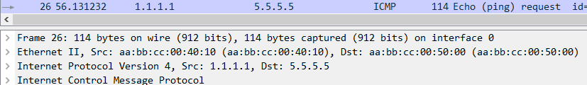
R1#ping 5.5.5.5 source 1.1.1.1 Type escape sequence to abort. Sending 5, 100-byte ICMP Echos to 5.5.5.5, timeout is 2 seconds: Packet sent with a source address of 1.1.1.1 !!!!! Success rate is 100 percent (5/5), round-trip min/avg/max = 1/1/2 ms
R3#show mpls forwarding-table Local Outgoing Prefix Bytes Label Outgoing Next Hop Label Label or Tunnel Id Switched interface 300 Pop Label 2.2.2.2/32 47030 Et0/0 10.1.23.2 301 Pop Label 4.4.4.4/32 46161 Et0/1 10.1.34.4
Routing Table: CISCO Codes: L - local, C - connected, S - static, R - RIP, M - mobile, B - BGP D - EIGRP, EX - EIGRP external, O - OSPF, IA - OSPF inter area N1 - OSPF NSSA external type 1, N2 - OSPF NSSA external type 2 E1 - OSPF external type 1, E2 - OSPF external type 2 i - IS-IS, su - IS-IS summary, L1 - IS-IS level-1, L2 - IS-IS level-2 ia - IS-IS inter area, * - candidate default, U - per-user static route o - ODR, P - periodic downloaded static route, H - NHRP, l - LISP a - application route + - replicated route, % - next hop override
Gateway of last resort is not set
1.0.0.0/32 is subnetted, 1 subnets D 1.1.1.1 [90/409600] via 10.1.12.1, 03:55:39, Ethernet0/0 5.0.0.0/32 is subnetted, 1 subnets B 5.5.5.5 [200/11] via 4.4.4.4, 00:08:05
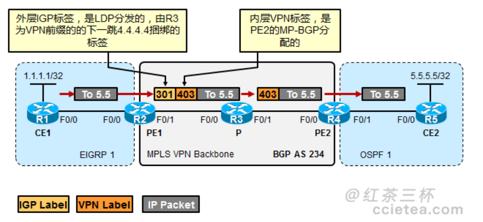
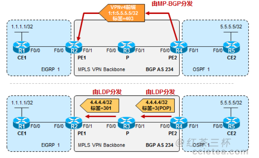
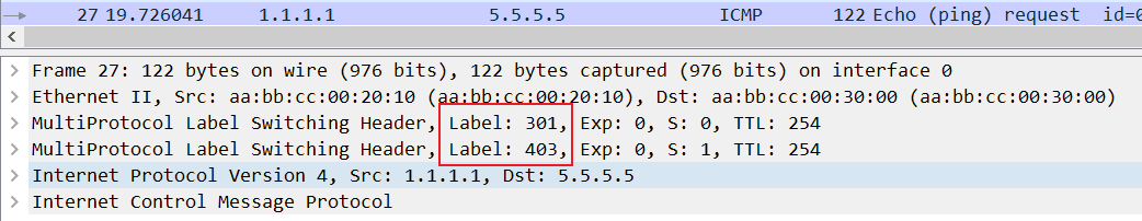
所以PE1这里使用的是P路由器(R3)分配给4.4.4.4的标签:
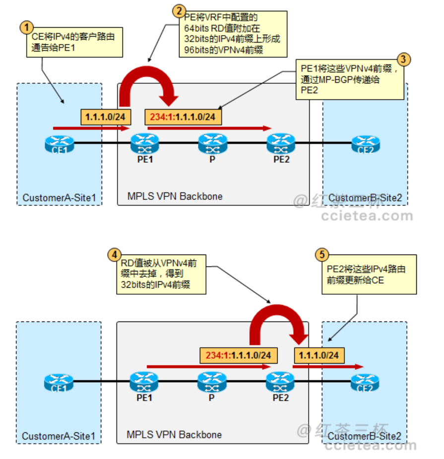
1 2 3 4 5
R3#show mpls forwarding-table
Local      Outgoing   Prefix           Bytes Label   Outgoing   Next Hop
Label      Label      or Tunnel Id     Switched      interface
300        Pop Label  2.2.2.2/32       9364          Et0/0      10.1.23.2
301        Pop Label  4.4.4.4/32       8552          Et0/1      10.1.34.4
所以这里捆绑的是R3给4.4.4.4分配的标签301。
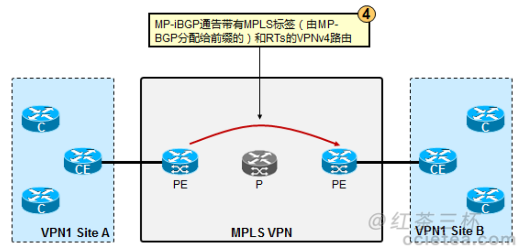
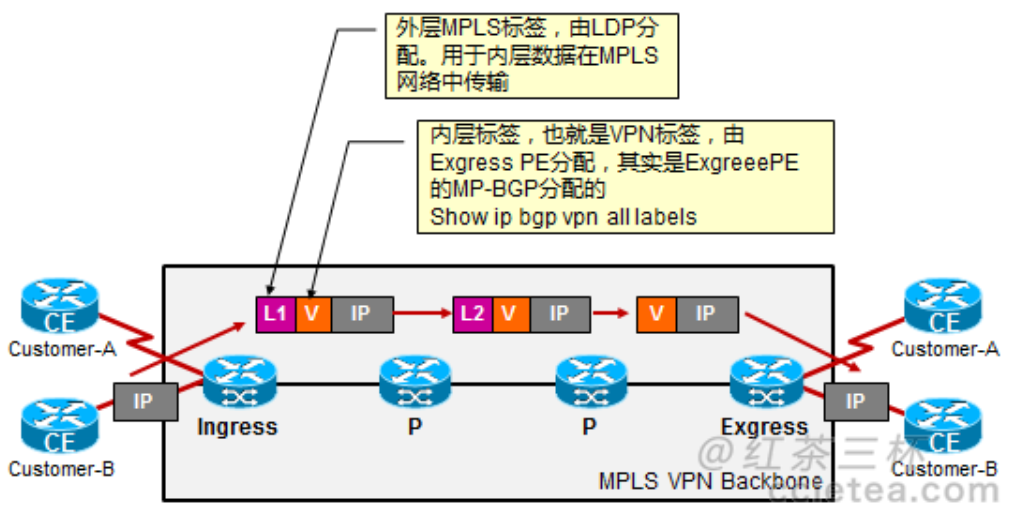
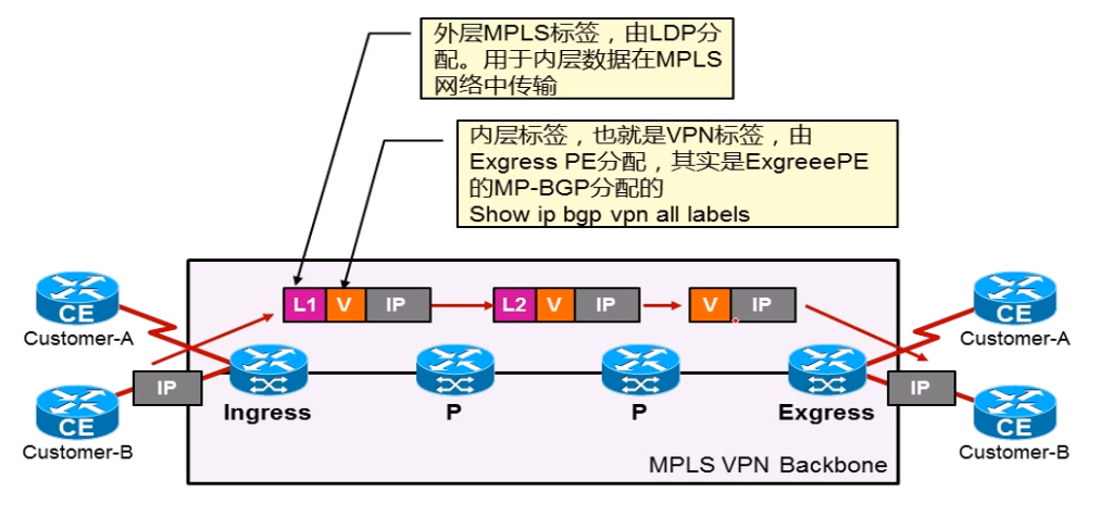
MP-BGP
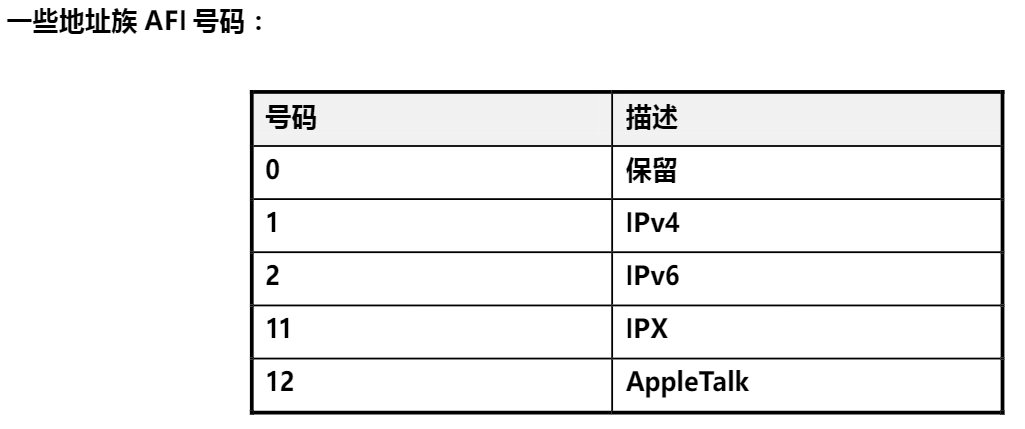
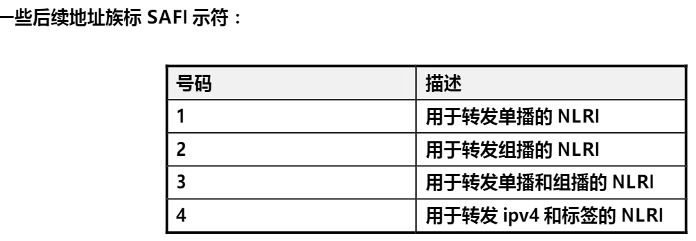
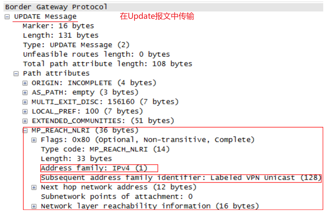
MP-BGP全称是‘Multiprotocol Extensions for BGP’。BGP的多协议扩展为BGP定义了两个新的属性:多协议可达NLRI以及多协议不可达NLRI,两个属性分别用来通告路由和退回路由。两个属性都维护着两个字段:地址簇标识符AFI(Address Family Indicator)、后续地址簇标识符SAFI(Subsequent Address Family Indicator)。这两个字段用来描述BGP所承载的是什么类型的路由。
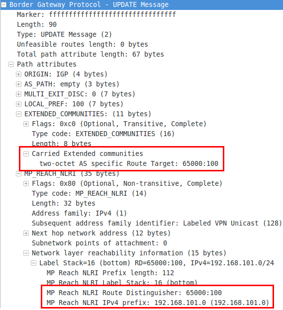
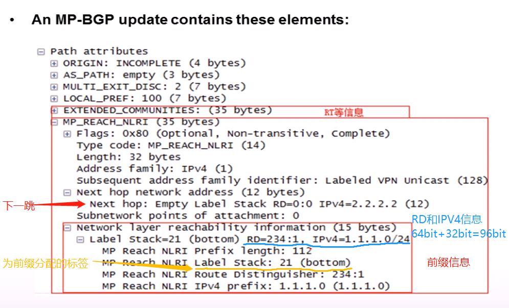
MP-BGP的Update中包含:
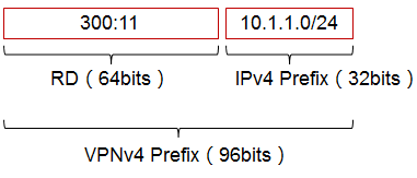
VPNV4前缀
扩展Community值:RTs、SOO….
Label used for VPN packets forwarding
其他常规BGP路径属性:MED、LP、AS_PATH、Origin、Standerd community
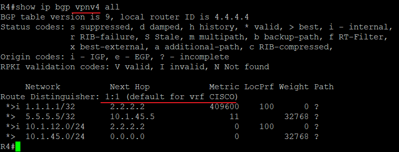
R4#show ip bgp vpnv4 all BGP table version is 9, local router ID is 4.4.4.4 Status codes: s suppressed, d damped, h history, * valid, > best, i - internal, r RIB-failure, S Stale, m multipath, b backup-path, f RT-Filter, x best-external, a additional-path, c RIB-compressed, Origin codes: i - IGP, e - EGP, ? - incomplete RPKI validation codes: V valid, I invalid, N Not found
CE1#show ip route Codes: L - local, C - connected, S - static, R - RIP, M - mobile, B - BGP D - EIGRP, EX - EIGRP external, O - OSPF, IA - OSPF inter area N1 - OSPF NSSA external type 1, N2 - OSPF NSSA external type 2 E1 - OSPF external type 1, E2 - OSPF external type 2 i - IS-IS, su - IS-IS summary, L1 - IS-IS level-1, L2 - IS-IS level-2 ia - IS-IS inter area, * - candidate default, U - per-user static route o - ODR, P - periodic downloaded static route, H - NHRP, l - LISP a - application route + - replicated route, % - next hop override, p - overrides from PfR
Gateway of last resort is not set
1.0.0.0/8 is variably subnetted, 3 subnets, 2 masks C 1.1.1.1/32 is directly connected, Loopback0 C 1.1.2.0/24 is directly connected, Loopback2 L 1.1.2.5/32 is directly connected, Loopback2 5.0.0.0/32 is subnetted, 1 subnets O E2 5.5.5.5 [110/20] via 192.168.14.1, 00:08:55, Ethernet0/0 192.168.14.0/24 is variably subnetted, 2 subnets, 2 masks C 192.168.14.0/24 is directly connected, Ethernet0/0 L 192.168.14.4/32 is directly connected, Ethernet0/0 O IA 192.168.25.0/24 [110/11] via 192.168.14.1, 00:08:55, Ethernet0/0
CE2#show ip route Codes: L - local, C - connected, S - static, R - RIP, M - mobile, B - BGP D - EIGRP, EX - EIGRP external, O - OSPF, IA - OSPF inter area N1 - OSPF NSSA external type 1, N2 - OSPF NSSA external type 2 E1 - OSPF external type 1, E2 - OSPF external type 2 i - IS-IS, su - IS-IS summary, L1 - IS-IS level-1, L2 - IS-IS level-2 ia - IS-IS inter area, * - candidate default, U - per-user static route o - ODR, P - periodic downloaded static route, H - NHRP, l - LISP a - application route + - replicated route, % - next hop override, p - overrides from PfR
Gateway of last resort is not set
1.0.0.0/32 is subnetted, 2 subnets O IA 1.1.1.1 [110/21] via 192.168.25.2, 00:08:53, Ethernet0/0 O IA 1.1.2.5 [110/21] via 192.168.25.2, 00:08:53, Ethernet0/0 5.0.0.0/32 is subnetted, 1 subnets C 5.5.5.5 is directly connected, Loopback0 O IA 192.168.14.0/24 [110/11] via 192.168.25.2, 00:08:53, Ethernet0/0 192.168.25.0/24 is variably subnetted, 2 subnets, 2 masks C 192.168.25.0/24 is directly connected, Ethernet0/0 L 192.168.25.5/32 is directly connected, Ethernet0/0
CE2#show ip route Codes: L - local, C - connected, S - static, R - RIP, M - mobile, B - BGP D - EIGRP, EX - EIGRP external, O - OSPF, IA - OSPF inter area N1 - OSPF NSSA external type 1, N2 - OSPF NSSA external type 2 E1 - OSPF external type 1, E2 - OSPF external type 2 i - IS-IS, su - IS-IS summary, L1 - IS-IS level-1, L2 - IS-IS level-2 ia - IS-IS inter area, * - candidate default, U - per-user static route o - ODR, P - periodic downloaded static route, H - NHRP, l - LISP a - application route + - replicated route, % - next hop override, p - overrides from PfR
Gateway of last resort is not set
1.0.0.0/32 is subnetted, 2 subnets O E2 1.1.1.1 [110/11] via 192.168.25.2, 00:00:26, Ethernet0/0 O E2 1.1.2.5 [110/11] via 192.168.25.2, 00:00:26, Ethernet0/0
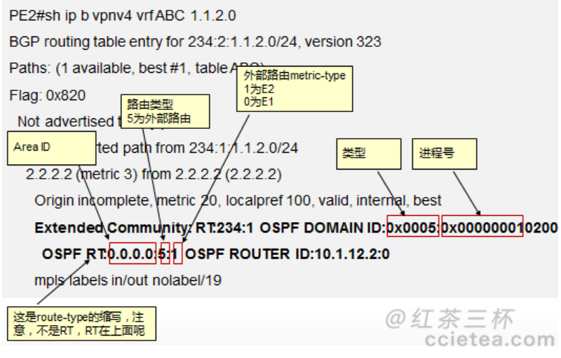
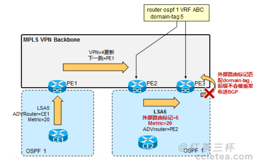
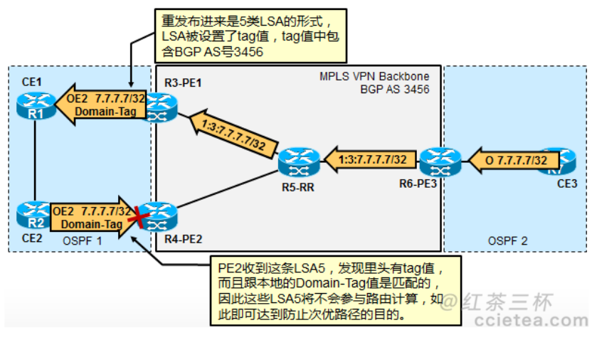
R5#sh ip ro 1.1.2.0 Routing entry for 1.1.2.0/24 Known via "ospf 1", distance 110, metric 20 Tag Complete, Path Length == 1, AS 234, , type extern 2, forward metric 1 Last update from 10.1.45.4 on FastEthernet0/0, 00:00:00 ago Routing Descriptor Blocks: * 10.1.45.4, from 44.44.44.44, 00:00:00 ago, via FastEthernet0/0 Route metric is 20, traffic share count is 1 Route tag 3489661162
PE1#show ip bgp vpnv4 all BGP table version is 4, local router ID is 2.2.2.2 Status codes: s suppressed, d damped, h history, * valid, > best, i - internal, r RIB-failure, S Stale, m multipath, b backup-path, f RT-Filter, x best-external, a additional-path, c RIB-compressed, t secondary path, Origin codes: i - IGP, e - EGP, ? - incomplete RPKI validation codes: V valid, I invalid, N Not found
Network Next Hop Metric LocPrf Weight Path Route Distinguisher: 1:1 (default for vrf CISCO) *> 1.1.1.1/32 192.168.12.1 0 0 12 i *>i 5.5.5.5/32 4.4.4.4 0 100 0 12 i
PE2#show ip bgp vpnv4 all BGP table version is 4, local router ID is 4.4.4.4 Status codes: s suppressed, d damped, h history, * valid, > best, i - internal, r RIB-failure, S Stale, m multipath, b backup-path, f RT-Filter, x best-external, a additional-path, c RIB-compressed, t secondary path, Origin codes: i - IGP, e - EGP, ? - incomplete RPKI validation codes: V valid, I invalid, N Not found
Network Next Hop Metric LocPrf Weight Path Route Distinguisher: 1:1 (default for vrf CISCO) *>i 1.1.1.1/32 2.2.2.2 0 100 0 12 i *> 5.5.5.5/32 192.168.45.5 0 0 12 i
PE1#show ip bgp vpnv4 all neighbors 192.168.12.1 advertised-routes BGP table version is 4, local router ID is 2.2.2.2 Status codes: s suppressed, d damped, h history, * valid, > best, i - internal, r RIB-failure, S Stale, m multipath, b backup-path, f RT-Filter, x best-external, a additional-path, c RIB-compressed, t secondary path, Origin codes: i - IGP, e - EGP, ? - incomplete RPKI validation codes: V valid, I invalid, N Not found
Network Next Hop Metric LocPrf Weight Path Route Distinguisher: 1:1 (default for vrf CISCO) *>i 5.5.5.5/32 4.4.4.4 0 100 0 12 i
Total number of prefixes 1
PE2#show ip bgp vpnv4 all neighbors 192.168.45.5 advertised-routes BGP table version is 4, local router ID is 4.4.4.4 Status codes: s suppressed, d damped, h history, * valid, > best, i - internal, r RIB-failure, S Stale, m multipath, b backup-path, f RT-Filter, x best-external, a additional-path, c RIB-compressed, t secondary path, Origin codes: i - IGP, e - EGP, ? - incomplete RPKI validation codes: V valid, I invalid, N Not found
Network Next Hop Metric LocPrf Weight Path Route Distinguisher: 1:1 (default for vrf CISCO) *>i 1.1.1.1/32 2.2.2.2 0 100 0 12 i
CE1# show ip bgp BGP table version is 2, local router ID is 1.1.1.1 Status codes: s suppressed, d damped, h history, * valid, > best, i - internal, r RIB-failure, S Stale, m multipath, b backup-path, f RT-Filter, x best-external, a additional-path, c RIB-compressed, t secondary path, Origin codes: i - IGP, e - EGP, ? - incomplete RPKI validation codes: V valid, I invalid, N Not found
Network Next Hop Metric LocPrf Weight Path *> 1.1.1.1/32 0.0.0.0 0 32768 i
CE2#show ip bgp BGP table version is 2, local router ID is 5.5.5.5 Status codes: s suppressed, d damped, h history, * valid, > best, i - internal, r RIB-failure, S Stale, m multipath, b backup-path, f RT-Filter, x best-external, a additional-path, c RIB-compressed, t secondary path, Origin codes: i - IGP, e - EGP, ? - incomplete RPKI validation codes: V valid, I invalid, N Not found
Network Next Hop Metric LocPrf Weight Path *> 5.5.5.5/32 0.0.0.0 0 32768 i
CE1上的debug如下: CE1# BGP(0): Revise route installing 1 of 1 routes for 5.5.5.5/32 -> 192.168.12.2(global) to main IP table
然后再看CE1和CE2的路由表: CE1#show ip route 5.5.5.5 Routing entry for 5.5.5.5/32 Known via "bgp 12", distance 20, metric 0 Tag 234, type external Last update from 192.168.12.2 00:01:46 ago Routing Descriptor Blocks: * 192.168.12.2, from 192.168.12.2, 00:01:46 ago Route metric is 0, traffic share count is 1 AS Hops 2 Route tag 234 MPLS label: none
CE2#show ip route 1.1.1.1 Routing entry for 1.1.1.1/32 Known via "bgp 12", distance 20, metric 0 Tag 234, type external Last update from 192.168.45.4 00:01:55 ago Routing Descriptor Blocks: * 192.168.45.4, from 192.168.45.4, 00:01:55 ago Route metric is 0, traffic share count is 1 AS Hops 2 Route tag 234 MPLS label: none
CE2#ping 1.1.1.1 source loop 0 Type escape sequence to abort. Sending 5, 100-byte ICMP Echos to 1.1.1.1, timeout is 2 seconds: Packet sent with a source address of 5.5.5.5 !!!!! 两侧也顺利ping通
PE1#show ip bgp all neighbors 192.168.12.1 advertised-routes For address family: VPNv4 Unicast BGP table version is 7, local router ID is 2.2.2.2 Status codes: s suppressed, d damped, h history, * valid, > best, i - internal, r RIB-failure, S Stale, m multipath, b backup-path, f RT-Filter, x best-external, a additional-path, c RIB-compressed, t secondary path, Origin codes: i - IGP, e - EGP, ? - incomplete RPKI validation codes: V valid, I invalid, N Not found
Network Next Hop Metric LocPrf Weight Path Route Distinguisher: 1:1 (default for vrf CISCO) *>i 5.5.5.5/32 4.4.4.4 0 100 0 12 i
PE2#show ip bgp vpnv4 all neighbors 192.168.45.5 advertised-routes BGP table version is 4, local router ID is 4.4.4.4 Status codes: s suppressed, d damped, h history, * valid, > best, i - internal, r RIB-failure, S Stale, m multipath, b backup-path, f RT-Filter, x best-external, a additional-path, c RIB-compressed, t secondary path, Origin codes: i - IGP, e - EGP, ? - incomplete RPKI validation codes: V valid, I invalid, N Not found
Network Next Hop Metric LocPrf Weight Path Route Distinguisher: 1:1 (default for vrf CISCO) *>i 1.1.1.1/32 2.2.2.2 0 100 0 12 i
CE1#show ip bgp BGP table version is 2, local router ID is 1.1.1.1 Status codes: s suppressed, d damped, h history, * valid, > best, i - internal, r RIB-failure, S Stale, m multipath, b backup-path, f RT-Filter, x best-external, a additional-path, c RIB-compressed, t secondary path, Origin codes: i - IGP, e - EGP, ? - incomplete RPKI validation codes: V valid, I invalid, N Not found
Network Next Hop Metric LocPrf Weight Path *> 1.1.1.1/32 0.0.0.0 0 32768 i
CE2#show ip bgp BGP table version is 2, local router ID is 5.5.5.5 Status codes: s suppressed, d damped, h history, * valid, > best, i - internal, r RIB-failure, S Stale, m multipath, b backup-path, f RT-Filter, x best-external, a additional-path, c RIB-compressed, t secondary path, Origin codes: i - IGP, e - EGP, ? - incomplete RPKI validation codes: V valid, I invalid, N Not found
Network Next Hop Metric LocPrf Weight Path *> 5.5.5.5/32 0.0.0.0 0 32768 i
CE1#show ip bgp BGP table version is 3, local router ID is 1.1.1.1 Status codes: s suppressed, d damped, h history, * valid, > best, i - internal, r RIB-failure, S Stale, m multipath, b backup-path, f RT-Filter, x best-external, a additional-path, c RIB-compressed, t secondary path, Origin codes: i - IGP, e - EGP, ? - incomplete RPKI validation codes: V valid, I invalid, N Not found
Network Next Hop Metric LocPrf Weight Path *> 1.1.1.1/32 0.0.0.0 0 32768 i *> 5.5.5.5/32 192.168.12.2 0 234 234 i
CE2#show ip bgp BGP table version is 3, local router ID is 5.5.5.5 Status codes: s suppressed, d damped, h history, * valid, > best, i - internal, r RIB-failure, S Stale, m multipath, b backup-path, f RT-Filter, x best-external, a additional-path, c RIB-compressed, t secondary path, Origin codes: i - IGP, e - EGP, ? - incomplete RPKI validation codes: V valid, I invalid, N Not found
Network Next Hop Metric LocPrf Weight Path *> 1.1.1.1/32 192.168.45.4 0 234 234 i *> 5.5.5.5/32 0.0.0.0 0 32768 i
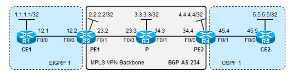
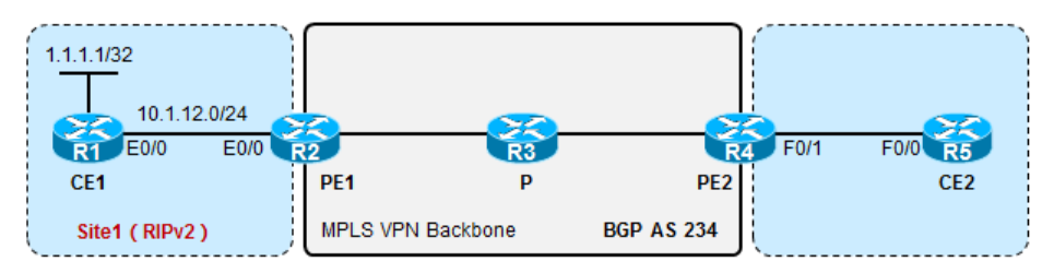
R1: interface Loopback0 ip address 1.1.1.1 255.255.255.255 ! interface Ethernet0/0 ip address 10.1.13.1 255.255.255.0 duplex auto ! interface Ethernet0/1 ip address 10.1.12.1 255.255.255.0 duplex auto ! interface Ethernet0/2 no ip address shutdown duplex auto ! interface Ethernet0/3 no ip address shutdown duplex auto ! router ospf 1 router-id 1.1.1.1 network 1.1.1.1 0.0.0.0 area 0 network 10.1.12.1 0.0.0.0 area 0 network 10.1.13.1 0.0.0.0 area 0
R2: interface Loopback0 ip address 2.2.2.2 255.255.255.255 ! interface Ethernet0/0 ip address 10.1.24.2 255.255.255.0 duplex auto ! interface Ethernet0/1 ip address 10.1.12.2 255.255.255.0 duplex auto ! interface Ethernet0/2 no ip address shutdown duplex auto ! interface Ethernet0/3 no ip address shutdown duplex auto ! router ospf 1 router-id 2.2.2.2 network 2.2.2.2 0.0.0.0 area 0 network 10.1.12.2 0.0.0.0 area 0 network 10.1.24.2 0.0.0.0 area 0
R3: ip vrf CISCO rd 1:1 route-target export 3456:12 route-target import 3456:3 route-target import 3456:12 ! ip cef no ipv6 cef ! multilink bundle-name authenticated mpls label range 300 399 ! interface Loopback0 ip address 3.3.3.3 255.255.255.255 ! interface Ethernet0/0 ip vrf forwarding CISCO ip address 10.1.13.3 255.255.255.0 duplex auto ! interface Ethernet0/1 ip address 10.1.35.3 255.255.255.0 duplex auto mpls ip ! interface Ethernet0/2 no ip address shutdown duplex auto ! interface Ethernet0/3 no ip address shutdown duplex auto ! router ospf 1 vrf CISCO redistribute bgp 3456 subnets network 10.1.13.3 0.0.0.0 area 0 ! router ospf 3456 router-id 3.3.3.3 network 3.3.3.3 0.0.0.0 area 0 network 10.1.35.3 0.0.0.0 area 0 ! router bgp 3456 bgp router-id 3.3.3.3 bgp log-neighbor-changes no bgp default ipv4-unicast neighbor 5.5.5.5 remote-as 3456 neighbor 5.5.5.5 update-source Loopback0 ! address-family vpnv4 neighbor 5.5.5.5 activate neighbor 5.5.5.5 send-community extended exit-address-family ! address-family ipv4 vrf CISCO redistribute ospf 1 match internal external 1 external 2 exit-address-family ! ip forward-protocol nd ! ! no ip http server no ip http secure-server ! ipv6 ioam timestamp ! ! mpls ldp router-id Loopback0
R4: ip vrf CISCO rd 1:2 route-target export 3456:12 route-target import 3456:12 route-target import 3456:3 ! ip cef no ipv6 cef ! multilink bundle-name authenticated mpls label range 400 499 ! interface Loopback0 ip address 4.4.4.4 255.255.255.255 ! interface Ethernet0/0 ip vrf forwarding CISCO ip address 10.1.24.4 255.255.255.0 duplex auto ! interface Ethernet0/1 ip address 10.1.45.4 255.255.255.0 duplex auto mpls ip ! interface Ethernet0/2 no ip address shutdown duplex auto ! interface Ethernet0/3 no ip address shutdown duplex auto ! router ospf 1 vrf CISCO redistribute bgp 3456 subnets network 10.1.24.4 0.0.0.0 area 0 ! router ospf 3456 router-id 4.4.4.4 network 4.4.4.4 0.0.0.0 area 0 network 10.1.45.4 0.0.0.0 area 0 ! router bgp 3456 bgp router-id 4.4.4.4 bgp log-neighbor-changes no bgp default ipv4-unicast neighbor 5.5.5.5 remote-as 3456 neighbor 5.5.5.5 update-source Loopback0 ! address-family vpnv4 neighbor 5.5.5.5 activate neighbor 5.5.5.5 send-community extended exit-address-family ! address-family ipv4 vrf CISCO redistribute ospf 1 match internal external 1 external 2 exit-address-family ! ip forward-protocol nd ! ! no ip http server no ip http secure-server ! ipv6 ioam timestamp ! ! mpls ldp router-id Loopback0
R5: interface Loopback0 ip address 5.5.5.5 255.255.255.255 ! interface Ethernet0/0 ip address 10.1.35.5 255.255.255.0 duplex auto mpls ip ! interface Ethernet0/1 ip address 10.1.45.5 255.255.255.0 duplex auto mpls ip ! interface Ethernet0/2 --More-- *Mar 27 17:33:26.911: %SYS-5-CONFIG_I: Configured from console by console ip address 10.1.56.5 255.255.255.0 duplex auto mpls ip ! interface Ethernet0/3 no ip address shutdown duplex auto ! router ospf 3456 router-id 5.5.5.5 network 0.0.0.0 255.255.255.255 area 0 ! router bgp 3456 bgp router-id 5.5.5.5 bgp log-neighbor-changes no bgp default ipv4-unicast neighbor 3.3.3.3 remote-as 3456 neighbor 3.3.3.3 update-source Loopback0 neighbor 4.4.4.4 remote-as 3456 neighbor 4.4.4.4 update-source Loopback0 neighbor 6.6.6.6 remote-as 3456 neighbor 6.6.6.6 update-source Loopback0 ! address-family vpnv4 neighbor 3.3.3.3 activate neighbor 3.3.3.3 send-community extended neighbor 3.3.3.3 route-reflector-client neighbor 4.4.4.4 activate neighbor 4.4.4.4 send-community extended neighbor 4.4.4.4 route-reflector-client neighbor 6.6.6.6 activate neighbor 6.6.6.6 send-community extended neighbor 6.6.6.6 route-reflector-client exit-address-family ! ip forward-protocol nd ! ! no ip http server no ip http secure-server ! ipv6 ioam timestamp ! ! mpls ldp router-id Loopback0
R6: ip vrf CISCO rd 1:3 route-target export 3456:3 route-target import 3456:12 ! ip cef no ipv6 cef ! multilink bundle-name authenticated mpls label range 600 699 ! interface Loopback0 ip address 6.6.6.6 255.255.255.255 ! interface Ethernet0/0 ip address 10.1.56.6 255.255.255.0 duplex auto mpls ip ! interface Ethernet0/1 ip vrf forwarding CISCO ip address 10.1.67.6 255.255.255.0 duplex auto ! interface Ethernet0/2 no ip address shutdown duplex auto ! interface Ethernet0/3 no ip address shutdown duplex auto ! router ospf 1 vrf CISCO redistribute bgp 3456 subnets network 10.1.67.6 0.0.0.0 area 0 ! router ospf 3456 router-id 6.6.6.6 network 6.6.6.6 0.0.0.0 area 0 network 10.1.56.6 0.0.0.0 area 0 ! router bgp 3456 bgp router-id 6.6.6.6 bgp log-neighbor-changes no bgp default ipv4-unicast neighbor 5.5.5.5 remote-as 3456 neighbor 5.5.5.5 update-source Loopback0 ! address-family vpnv4 neighbor 5.5.5.5 activate neighbor 5.5.5.5 send-community extended exit-address-family ! address-family ipv4 vrf CISCO redistribute ospf 1 match internal external 1 external 2 exit-address-family ! ip forward-protocol nd ! ! no ip http server no ip http secure-server ! ipv6 ioam timestamp ! ! mpls ldp router-id Loopback0
R7: interface Loopback0 ip address 7.7.7.7 255.255.255.255 ! interface Ethernet0/0 ip address 10.1.67.7 255.255.255.0 duplex auto ! interface Ethernet0/1 no ip address shutdown duplex auto ! interface Ethernet0/2 no ip address shutdown duplex auto ! interface Ethernet0/3 no ip address shutdown duplex auto ! router ospf 1 router-id 7.7.7.7 network 7.7.7.7 0.0.0.0 area 0 network 10.1.67.7 0.0.0.0 area 0
B 1.1.1.1 [200/11] via 3.3.3.3, 01:27:08 B 1.1.1.1 [200/11] via 3.3.3.3, 01:27:08 B 7.7.7.7 [200/11] via 6.6.6.6, 01:27:08 B 10.1.12.0/24 [200/20] via 3.3.3.3, 01:27:08 B 10.1.13.0/24 [200/0] via 3.3.3.3, 01:27:08 B 10.1.67.0/24 [200/0] via 6.6.6.6, 01:27:08
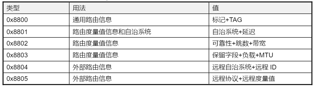
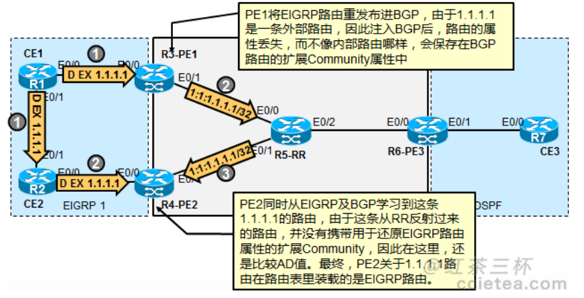
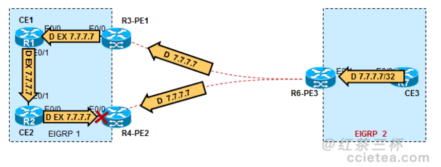
R3-PE1#sh ip b vpnv4 all 1.1.1.1 BGP routing table entry for 1:1:1.1.1.1/32, version 1072 Paths: (1 available, best #1, table cisco) Advertised to update-groups: 4 Local 10.1.13.1 from 0.0.0.0 (3.3.3.3) Origin incomplete, metric 409600, localpref 100, weight 32768, valid, sourced, best 0x8800:32768:0 0x8801:1:153600 0x8802:65281:256000 0x8803:65281:1500 !! 丰富的扩展 community 值很好的保护了 EIGRP 路由的原始生态特征 mpls labels in/out 313/nolabel
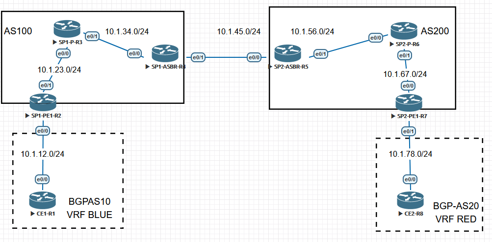
SP1-PE1-R2: interface Loopback0 ip address 2.2.2.2 255.255.255.255 ! interface Ethernet0/0 ip address 10.1.12.2 255.255.255.0 duplex auto ! interface Ethernet0/1 ip address 10.1.23.2 255.255.255.0 ! router ospf 1 network 2.2.2.2 0.0.0.0 area 0 network 10.1.23.2 0.0.0.0 area 0
SP1-P-R3: interface Loopback0 ip address 3.3.3.3 255.255.255.255 ! interface Ethernet0/0 ip address 10.1.23.3 255.255.255.0 ! interface Ethernet0/1 ip address 10.1.34.3 255.255.255.0 ! router ospf 1 router-id 3.3.3.3 network 0.0.0.0 255.255.255.255 area 0
SP1-ASBR-R4: interface Loopback0 ip address 4.4.4.4 255.255.255.255 ! interface Ethernet0/0 ip address 10.1.34.4 255.255.255.0 duplex auto ! router ospf 1 router-id 4.4.4.4 network 4.4.4.4 0.0.0.0 area 0 network 10.1.34.4 0.0.0.0 area 0
SP2-ASBR-R5: interface Loopback0 ip address 5.5.5.5 255.255.255.255 ! interface Ethernet0/1 ip address 10.1.56.5 255.255.255.0 ! router ospf 567 router-id 5.5.5.5 network 5.5.5.5 0.0.0.0 area 0 network 10.1.56.5 0.0.0.0 area 0
SP2-P-R6: interface Loopback0 ip address 6.6.6.6 255.255.255.255 ! interface Ethernet0/0 ip address 10.1.56.6 255.255.255.0 ! interface Ethernet0/1 ip address 10.1.67.6 255.255.255.0 ! router ospf 567 router-id 6.6.6.6 network 0.0.0.0 255.255.255.255 area 0
SP2-PE1-R7: interface Loopback0 ip address 7.7.7.7 255.255.255.255 ! interface Ethernet0/0 ip address 10.1.67.7 255.255.255.0 duplex auto ! interface Ethernet0/1 no ip address duplex auto ! router ospf 567 router-id 7.7.7.7 network 7.7.7.7 0.0.0.0 area 0 network 10.1.67.7 0.0.0.0 area 0
SP1-PE1-R2: ip vrf BLUE rd 100:100 route-target export 100:100 route-target import 100:100 ! interface Ethernet0/0 ip vrf forwarding BLUE ip address 10.1.12.2 255.255.255.0
验证VRF的配置: R2#show ip vrf Name Default RD Interfaces BLUE 100:100 Et0/0
验证是否收到了1.1.1.1路由 R2#show bgp vpnv4 unicast all BGP table version is 2, local router ID is 2.2.2.2 Status codes: s suppressed, d damped, h history, * valid, > best, i - internal, r RIB-failure, S Stale, m multipath, b backup-path, f RT-Filter, x best-external, a additional-path, c RIB-compressed, t secondary path, Origin codes: i - IGP, e - EGP, ? - incomplete RPKI validation codes: V valid, I invalid, N Not found
Network Next Hop Metric LocPrf Weight Path Route Distinguisher: 100:100 (default for vrf BLUE) *> 1.1.1.1/32 10.1.12.1 0 0 10 i
在SP2-PE1-R7上做类似的配置: ip vrf RED rd 200:200 route-target export 200:200 route-target import 200:200
interface Ethernet0/1 ip vrf forwarding RED ip address 10.1.78.7 255.255.255.0
R7#show ip vrf Name Default RD Interfaces RED 200:200 Et0/1
R7收到了8.8.8.8的路由: R7#show bgp vpnv4 unicast all BGP table version is 2, local router ID is 7.7.7.7 Status codes: s suppressed, d damped, h history, * valid, > best, i - internal, r RIB-failure, S Stale, m multipath, b backup-path, f RT-Filter, x best-external, a additional-path, c RIB-compressed, t secondary path, Origin codes: i - IGP, e - EGP, ? - incomplete RPKI validation codes: V valid, I invalid, N Not found
Network Next Hop Metric LocPrf Weight Path Route Distinguisher: 200:200 (default for vrf RED) *> 8.8.8.8/32 10.1.78.8 0 0 20 i
SP1-PE1-R2: router bgp 100 bgp router-id 2.2.2.2 no bgp default ipv4-unicast neighbor 4.4.4.4 remote-as 100 neighbor 4.4.4.4 update-source Loopback0 ! address-family vpnv4 neighbor 4.4.4.4 activate neighbor 4.4.4.4 send-community extended 来看PE1和ASBR之间的VPNV4邻居是否建立: R4#show ip bgp vpnv4 all summary BGP router identifier 4.4.4.4, local AS number 100 BGP table version is 3, main routing table version 3 1 network entries using 156 bytes of memory 1 path entries using 84 bytes of memory 1/1 BGP path/bestpath attribute entries using 168 bytes of memory 1 BGP AS-PATH entries using 24 bytes of memory 1 BGP extended community entries using 24 bytes of memory 0 BGP route-map cache entries using 0 bytes of memory 0 BGP filter-list cache entries using 0 bytes of memory BGP using 456 total bytes of memory BGP activity 1/0 prefixes, 1/0 paths, scan interval 60 secs
Neighbor V AS MsgRcvd MsgSent TblVer InQ OutQ Up/Down State/PfxRcd 2.2.2.2 4 100 28 27 3 0 0 00:21:39 1
验证ASBR是否收到了PE1发来的VPNV4路由: R4#show ip bgp vpnv4 all BGP table version is 3, local router ID is 4.4.4.4 Status codes: s suppressed, d damped, h history, * valid, > best, i - internal, r RIB-failure, S Stale, m multipath, b backup-path, f RT-Filter, x best-external, a additional-path, c RIB-compressed, t secondary path, Origin codes: i - IGP, e - EGP, ? - incomplete RPKI validation codes: V valid, I invalid, N Not found
Network Next Hop Metric LocPrf Weight Path Route Distinguisher: 100:100 (default for vrf BLUE) *>i 1.1.1.1/32 2.2.2.2 0 100 0 10 i
此时SP2-ASBR-R5也收到了8.8.8.8这条路由: R5#show bgp vpnv4 unicast all BGP table version is 3, local router ID is 5.5.5.5 Status codes: s suppressed, d damped, h history, * valid, > best, i - internal, r RIB-failure, S Stale, m multipath, b backup-path, f RT-Filter, x best-external, a additional-path, c RIB-compressed, t secondary path, Origin codes: i - IGP, e - EGP, ? - incomplete RPKI validation codes: V valid, I invalid, N Not found
Network Next Hop Metric LocPrf Weight Path Route Distinguisher: 200:200 (default for vrf RED) *>i 8.8.8.8/32 7.7.7.7 0 100 0 20 i
SP2-ASBR-R5: interface Ethernet0/0.100 encapsulation dot1Q 100 ip vrf forwarding RED ip address 10.1.45.5 255.255.255.0
SP1-ASBR-R4: interface Ethernet0/1.100 encapsulation dot1Q 100 ip vrf forwarding BLUE ip address 10.1.45.4 255.255.255.0
R4#ping vrf BLUE 10.1.45.5 Type escape sequence to abort. Sending 5, 100-byte ICMP Echos to 10.1.45.5, timeout is 2 seconds: .!!!! Success rate is 80 percent (4/5), round-trip min/avg/max = 1/1/1 ms
R5#show bgp vpnv4 unicast all BGP table version is 4, local router ID is 5.5.5.5 Status codes: s suppressed, d damped, h history, * valid, > best, i - internal, r RIB-failure, S Stale, m multipath, b backup-path, f RT-Filter, x best-external, a additional-path, c RIB-compressed, t secondary path, Origin codes: i - IGP, e - EGP, ? - incomplete RPKI validation codes: V valid, I invalid, N Not found
Network Next Hop Metric LocPrf Weight Path Route Distinguisher: 200:200 (default for vrf RED) *> 1.1.1.1/32 10.1.45.4 0 100 10 i *>i 8.8.8.8/32 7.7.7.7 0 100 0 20 i
R4#show bgp vpnv4 unicast all BGP table version is 4, local router ID is 4.4.4.4 Status codes: s suppressed, d damped, h history, * valid, > best, i - internal, r RIB-failure, S Stale, m multipath, b backup-path, f RT-Filter, x best-external, a additional-path, c RIB-compressed, t secondary path, Origin codes: i - IGP, e - EGP, ? - incomplete RPKI validation codes: V valid, I invalid, N Not found
Network Next Hop Metric LocPrf Weight Path Route Distinguisher: 100:100 (default for vrf BLUE) *>i 1.1.1.1/32 2.2.2.2 0 100 0 10 i *> 8.8.8.8/32 10.1.45.5 0 200 20 i
R2#show bgp vpnv4 unicast all BGP table version is 4, local router ID is 2.2.2.2 Status codes: s suppressed, d damped, h history, * valid, > best, i - internal, r RIB-failure, S Stale, m multipath, b backup-path, f RT-Filter, x best-external, a additional-path, c RIB-compressed, t secondary path, Origin codes: i - IGP, e - EGP, ? - incomplete RPKI validation codes: V valid, I invalid, N Not found
Network Next Hop Metric LocPrf Weight Path Route Distinguisher: 100:100 (default for vrf BLUE) *> 1.1.1.1/32 10.1.12.1 0 0 10 i *>i 8.8.8.8/32 4.4.4.4 0 100 0 200 20 i
R1#show ip route Codes: L - local, C - connected, S - static, R - RIP, M - mobile, B - BGP D - EIGRP, EX - EIGRP external, O - OSPF, IA - OSPF inter area N1 - OSPF NSSA external type 1, N2 - OSPF NSSA external type 2 E1 - OSPF external type 1, E2 - OSPF external type 2 i - IS-IS, su - IS-IS summary, L1 - IS-IS level-1, L2 - IS-IS level-2 ia - IS-IS inter area, * - candidate default, U - per-user static route o - ODR, P - periodic downloaded static route, H - NHRP, l - LISP a - application route + - replicated route, % - next hop override, p - overrides from PfR
Gateway of last resort is not set
1.0.0.0/32 is subnetted, 1 subnets C 1.1.1.1 is directly connected, Loopback0 8.0.0.0/32 is subnetted, 1 subnets B 8.8.8.8 [20/0] via 10.1.12.2, 00:05:57
R7#show bgp vpnv4 unicast all BGP table version is 4, local router ID is 7.7.7.7 Status codes: s suppressed, d damped, h history, * valid, > best, i - internal, r RIB-failure, S Stale, m multipath, b backup-path, f RT-Filter, x best-external, a additional-path, c RIB-compressed, t secondary path, Origin codes: i - IGP, e - EGP, ? - incomplete RPKI validation codes: V valid, I invalid, N Not found
Network Next Hop Metric LocPrf Weight Path Route Distinguisher: 200:200 (default for vrf RED) *>i 1.1.1.1/32 5.5.5.5 0 100 0 100 10 i *> 8.8.8.8/32 10.1.78.8 0 0 20 i
R8#show ip route Codes: L - local, C - connected, S - static, R - RIP, M - mobile, B - BGP D - EIGRP, EX - EIGRP external, O - OSPF, IA - OSPF inter area N1 - OSPF NSSA external type 1, N2 - OSPF NSSA external type 2 E1 - OSPF external type 1, E2 - OSPF external type 2 i - IS-IS, su - IS-IS summary, L1 - IS-IS level-1, L2 - IS-IS level-2 ia - IS-IS inter area, * - candidate default, U - per-user static route o - ODR, P - periodic downloaded static route, H - NHRP, l - LISP a - application route + - replicated route, % - next hop override, p - overrides from PfR
Gateway of last resort is not set
1.0.0.0/32 is subnetted, 1 subnets B 1.1.1.1 [20/0] via 10.1.78.7, 00:07:34
R2#show bgp vpnv4 unicast all BGP table version is 4, local router ID is 2.2.2.2 Status codes: s suppressed, d damped, h history, * valid, > best, i - internal, r RIB-failure, S Stale, m multipath, b backup-path, f RT-Filter, x best-external, a additional-path, c RIB-compressed, t secondary path, Origin codes: i - IGP, e - EGP, ? - incomplete RPKI validation codes: V valid, I invalid, N Not found
Network Next Hop Metric LocPrf Weight Path Route Distinguisher: 100:100 (default for vrf BLUE) *> 1.1.1.1/32 10.1.12.1 0 0 10 i *>i 8.8.8.8/32 4.4.4.4 0 100 0 200 20 i
R2#show mpls forwarding-table Local Outgoing Prefix Bytes Label Outgoing Next Hop Label Label or Tunnel Id Switched interface 201 302 4.4.4.4/32 0 Et0/1 10.1.23.3
内层标签由MP-BGP分配,具体来说就是由SP1-ASBR-R3分配:
1 2 3 4
R4#show mpls forwarding-table
Local      Outgoing   Prefix           Bytes Label   Outgoing   Next Hop
Label      Label      or Tunnel Id     Switched      interface
403        No Label   8.8.8.8/32[V]    2302          Et0/1.100  10.1.45.5
R3#show mpls forwarding-table
Local      Outgoing   Prefix           Bytes Label   Outgoing   Next Hop
Label      Label      or Tunnel Id     Switched      interface
302        Pop Label  4.4.4.4/32       42891         Et0/1      10.1.34.4
303        Pop Label  2.2.2.2/32       41172         Et0/0      10.1.23.2
R4#show mpls forwarding-table
Local      Outgoing   Prefix           Bytes Label   Outgoing   Next Hop
Label      Label      or Tunnel Id     Switched      interface
403        No Label   8.8.8.8/32[V]    2302          Et0/1.100  10.1.45.5
R5#show mpls forwarding-table
Local      Outgoing   Prefix           Bytes Label   Outgoing   Next Hop
Label      Label      or Tunnel Id     Switched      interface
503        602        7.7.7.7/32       0             Et0/1      10.1.56.6


R5#show ip route
      7.0.0.0/32 is subnetted, 1 subnets
O        7.7.7.7 [110/21] via 10.1.56.6, 06:47:19, Ethernet0/1


R5#show bgp vpnv4 unicast all
BGP table version is 4, local router ID is 5.5.5.5
Status codes: s suppressed, d damped, h history, * valid, > best, i - internal,
              r RIB-failure, S Stale, m multipath, b backup-path, f RT-Filter,
              x best-external, a additional-path, c RIB-compressed,
              t secondary path,
Origin codes: i - IGP, e - EGP, ? - incomplete
RPKI validation codes: V valid, I invalid, N Not found

     Network          Next Hop            Metric LocPrf Weight Path
Route Distinguisher: 200:200 (default for vrf RED)
 *>i  8.8.8.8/32       7.7.7.7                  0    100      0 20 i
R7#show mpls forwarding-table
Local      Outgoing   Prefix           Bytes Label   Outgoing   Next Hop
Label      Label      or Tunnel Id     Switched      interface
16         No Label   8.8.8.8/32[V]    1824          Et0/1      10.1.78.8
R6#show mpls forwarding-table
Local      Outgoing   Prefix           Bytes Label   Outgoing   Next Hop
Label      Label      or Tunnel Id     Switched      interface
602        Pop Label  7.7.7.7/32       52717         Et0/1      10.1.67.7
R7#show mpls forwarding-table
Local      Outgoing   Prefix           Bytes Label   Outgoing   Next Hop
Label      Label      or Tunnel Id     Switched      interface
16         No Label   8.8.8.8/32[V]    1824          Et0/1      10.1.78.8


 wechat
 alipay